
Printed Parts get the chance to publish the schemes of Prusai3 electronics, graphic visualization is given by the work we did Alberto Aragoneses Calvo, (member of Bitaq) also member of makespace. Thanks to him, because of this cooperation with Printed Parts
Quick guide for Ramps: Electronic connection for beginners
|
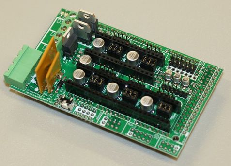
RAMPS 1.3 - 1.4
I took this picture from Wikipedia, we can get a couple of thoughts. Would I be able to connect everything without burning something? Would I need to know advanced electronics to make a 3D printer run? Answer to both questions can be No, but depends on your experience, The main purpose would be contact to your next/nearer local teacher, but does he start by basics? Wich level are you, beginner or advanced? |
Modular vision is given by thinking in different groups, not jumping into single individual things, it can be divided. Just different groups wich can help us to achieve understanding of our object. Active things or passive things? Getting into those zones, we can be interested on individual, singular things.
Basic way of thinking would not start by checking every single item of this electronics, but by making it easy to understand on different groups, and then... upgrade your level of knowledge later on. A 3D printer are quite a lot of elements. All of those are giving a single job wich is working at the same time of multiple others. If you get throught everything at the same time, you would not achieve that! You must start from a simple view.
Start thinking: A 3D printer is made just by four motors and five sensors, two heat sensors and three movement sensors, those work in perfect programmed armony!

POWER
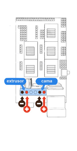
Ramps have different versions, also some Ramps are given as clone ones... not originals, but all of those have some common things, in this case, lower-right in green color, it is the part where our electronics get power from our power source. and also on lower-left in blue color the energy gets "out" to feed the bed and the extruder.
|
|
Power connections are quite sensitive, you need to double-check polarity, check on positive and negative poles are in right order, always.
Black will be Negative, Red as Positive, and make the screws quite well tight! Also, when you get a wire, try to tin the tips. (Wich I am not sure if its a proper expression.) Take care of small threads, must not contact anything but the singular connection you are using the cable for. |
MOTORS
|
stepper motor Is a kind of his own, it is called by that because it gives steps, you will need to program on the software you will use.
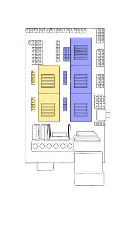
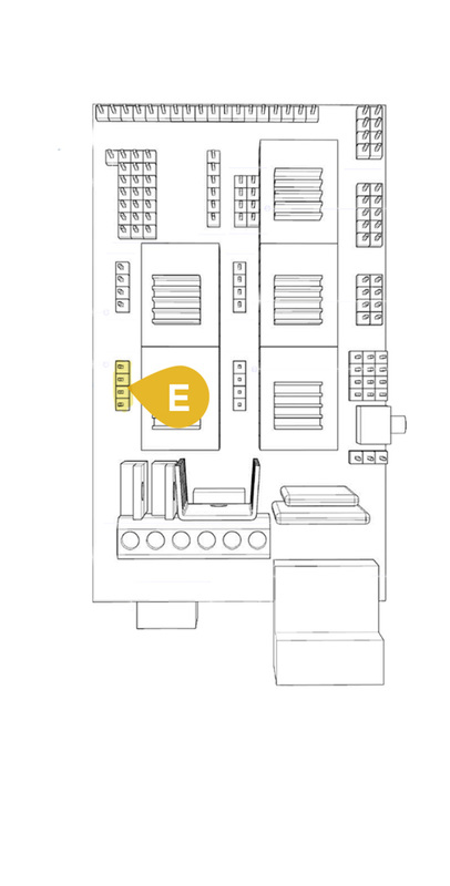
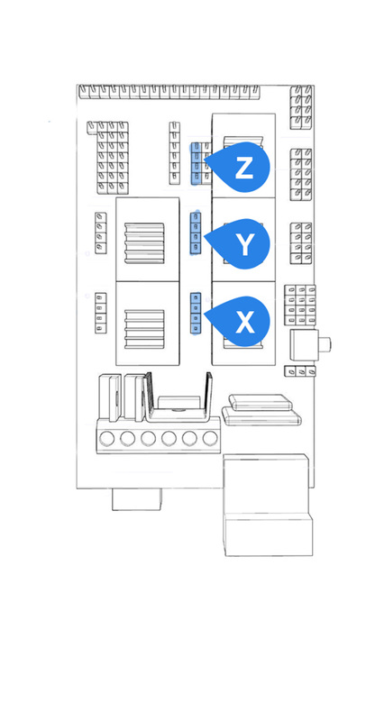
To connect motors, you would need to know just a couple of things, left parts in yellow are place for extruder motors, blue right part is for axis motors, those are read from bottom to the top as X, Y, Z. X Y Z AXIS in a 3D printer, (there is no standard with 3D software.. for all we 3D users have struggle with it) Z axis Vertical Y axis Base (near to far) X axis Horizontal (left to right) |
|
|
In this case, contoller from the left (the yellow one) have a unused motor on the top, it is just for people who want double extruder, and believe me.. you don't want that at the moment. But it is a plus.. when you want to choose between Arduino or other based electronics. Extra slot!
It is important to know, stepper motors have lots of cable, those come in pairs, circular sequence can be given just if those are in order, steps inside must be in correct order, depends on the model you have. If pairs are well, then it will move, but it depends forwards or backwards if you connect it upwards or downwards. (I mean.. pair1 and pair2 in slots 1,2 wich are checked by connecting the 4 pin one way or the opposite one) |
Sensors
We checked the power, how it will control those stepper motors, but none of those give information to the electronics to get know when to stop, when to stop moving or heating... so it need "senses", sensors, so those will say when to stop heating or stop moving, so the sensors are:
Endstop - This gives the stop by triggering a switch
Thermistor - Sensor of temperature by a resistor
Endstop - This gives the stop by triggering a switch
Thermistor - Sensor of temperature by a resistor
Endstops
|
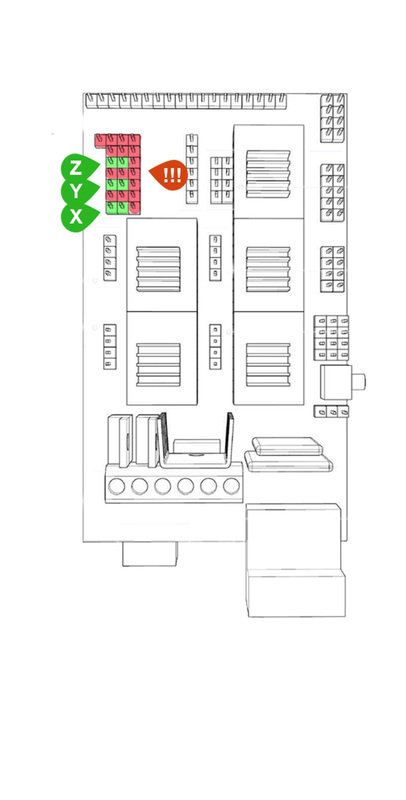
Endstops say where this (0,0,0) point is, where this home, or start point is given, and then the 3D printer will start moving or when it will stop moving.
We just need three, one per axis, because by programming we say not to move more than the 20cm given by programmed software, but always need to check where does it start! Take care of where you connect all those endstops! If you connect on red parts (represented on the scheme), it can burn Ramps, it can give real and faltal damage to the electronics, and then.. buy another Ramps or... even as well Arduino. Endstops are just a simple swich wich is closing a circuit, polarity is not important here, but it is not to touch any of the red pins, because we would provoke a short. Red pins were reserved for second endstops, but not many or none people I know use them. |
Thermistor
|
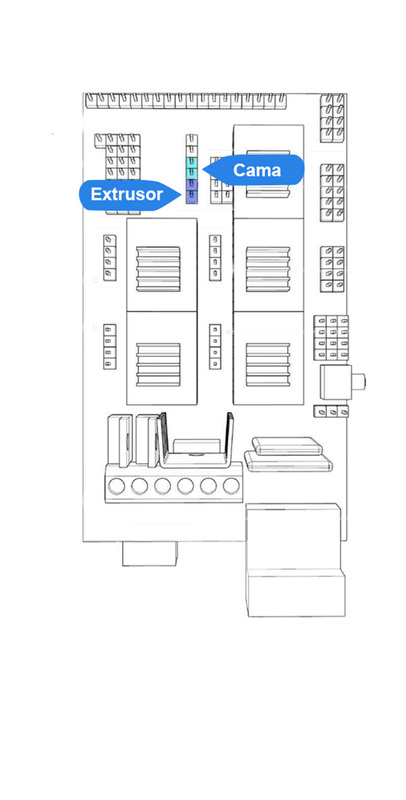
Thermistors are sensors, at 3D printing NTC thermistors are used, those work by lowering resistance by temperature given on the ambient.
Remember, when we heat from power supply, it is a different thing from it thermistor gives control to stop or to give sign of open power supply, it senses, and it has to communicate with the electronics to say, It's ok, its warm here enought! Depending on heat, the material given on this thermistor will allow current, it decrease current resistance, so when electricity passes throught easily, electronics now it is getting warm, and then it gives a data, given on knowing how this material reacts with heating. Bad connection will mark an error on LCD or won't let power going throught, so this gives a signal to the electronics to stop. If thermistor would not work properly... imagine electronics giving more electricity and raising temperature throught limits... It could reach quite high temperature and burn everything around. So it is important to make sensors work properly. |
If it is properly connected, ramps connected and mounted on Arduino, it will work "perfectly" In the case.. everything works or if its built properly.
There are more connections on other circuits given by the SSR, it allows current not passing through Ramps and maken it happen on different electric roads. Heated bed bigger than 20x20 would increase amperes coming through Ramps electronics, wich are not prepared to suffer such heavy job.
There are more connections on other circuits given by the SSR, it allows current not passing through Ramps and maken it happen on different electric roads. Heated bed bigger than 20x20 would increase amperes coming through Ramps electronics, wich are not prepared to suffer such heavy job.
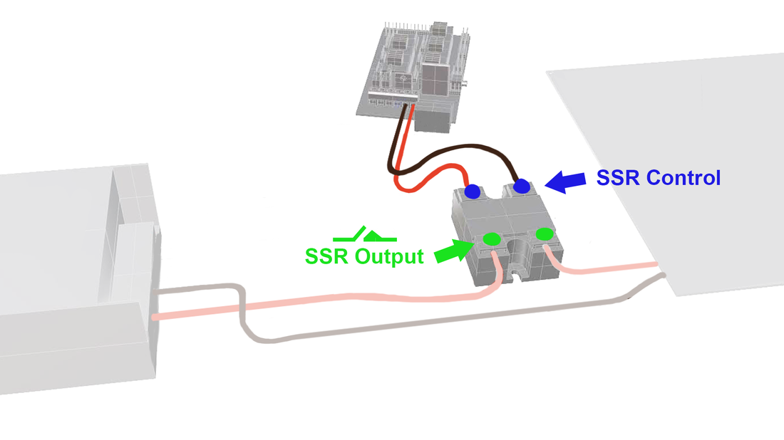
Installing a SSR
|
|
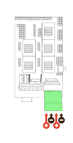
To install a SSR, depends if you are using a heated bed size quite bigger than 20 x 20, because all of the ampere coming throught it, this waste and damage connections on the electronics so it won't resist much without getting burned.
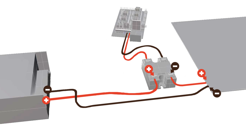
you have to check polarity installing those devices, Output is the given circuit for electric current, Control point would give a sign when to start or stop current, so it gives a small current to activate SSR, wich drives the actual current to the goal: The giant heated bed. So ramps, would work as a switch into the SSR to give this time signal.. when to start, when to stop giving current to the heated bed.
Ramps would close the circuit inside the SSR, so it allows current or not from power source to heated bed coming through SSR. Ramps just work as the boss of SSR by closing the circuit inside of it.
